PMSDR
A SDR-receiver from the italian SDR developers community:
low-cost “Software Defined Radio” full coverage receiver for all HF bands, 50MHz (6m Band) and 70MHz (4m band), used with powerful software on the PC for multi-mode operation
| DOWNCONVERTER & SWITCH PLUG-IN 2in1-BOARD for PMSDR 2.X |
It’s a complete downconverter for the VHF-UHF bands, covering from about 90 Mhz up to 500 Mhz. The board can be added to the PMSDR as an option, extending the frequency range up to 500 Mhz. There are two preselection filters, for VHF and UHF bands, but it’s also possible to exclude these filters in order to use external filters. A particular feature of this downconverter is the digitally tunable LO, from 10 up to 810 MHz; this allows use of a wide range of IF frequencies. Furthermore, the downconverter has also a build-in automatic T/R antenna switch, which permits use of a transceiver on the same antenna as the PMSDR (see Switchboard).
Furthermore, the downconverter have also a build-in automatic T/R antenna switch, which permit to use a transceiver on the same antenna with the PMSDR (see Switchboard).
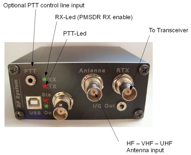
Normally the antenna is connected to the PMSDR input. When the unit senses RF power on RTX, the antenna is connected to the RTX input. Three operating modes are available: passive, manual and automatic mode. When the PMSDR is not powered, the transceiver is connected to the antenna to avoid damage to the transceiver.
Main features:
- No external power required – low power cosumption design
- Build-in antenna switch (Switchboard)
- Passthrough for Broadband input (to use with external filters)
- Wide range tunable VHF-filter (90 – 160 MHz)
- Tunable UHF-filter (420 – 460 MHz)
- Tunable LO (from 10 to 810MHz)

Switch function overview:
Passive Mode
The SDR-software disable the PTT control unit. So the antenna is always connected to the transceiver, and you can use the software to switch the antenna between the PMSDR or transceiver. This is the same condition when the PMSDR is not powered.
Manual Mode
Use the PTT control line of your transceiver connected to the optional PTT control line input. By grounding PTT, RTX. When the transceiver is connected to the antenna, the PMSDR RX input filters are disabled for better isolation. If PTT is open, the antenna is switched to the PMSDR RX input.
Automatic Mode
Don’t use the PTT control line. When the switch plug-in board senses RF power on the RTX input (HF-VOX), it automatically switches transceiver to the antenna, otherwise the antenna is connected to the PMSDR.
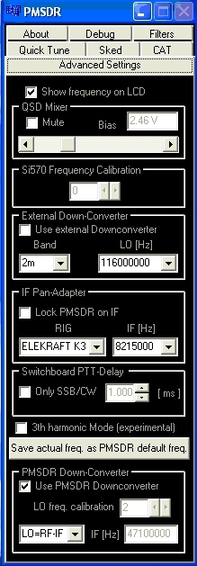
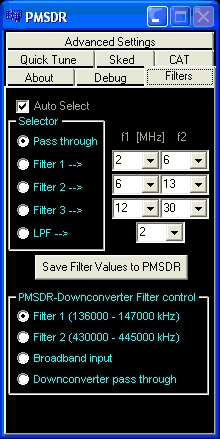
The audio output on Winrad/HDSDR can be muted automatically during the transmission. The Downconverter required a PMSDR firmware V2.1.8 or higher and the ExtIo_PMSDR.DLL V3.2 rev9 or higher. All filter selections is done automatically by software:
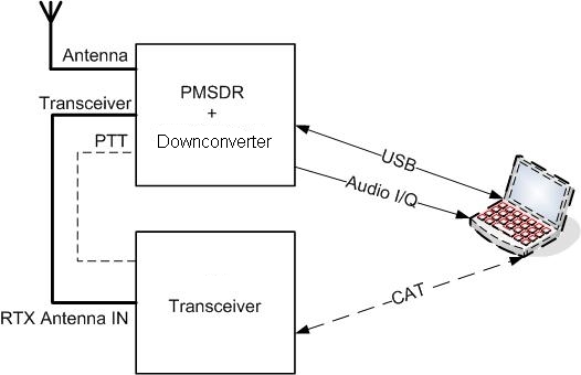
Tipical configuration
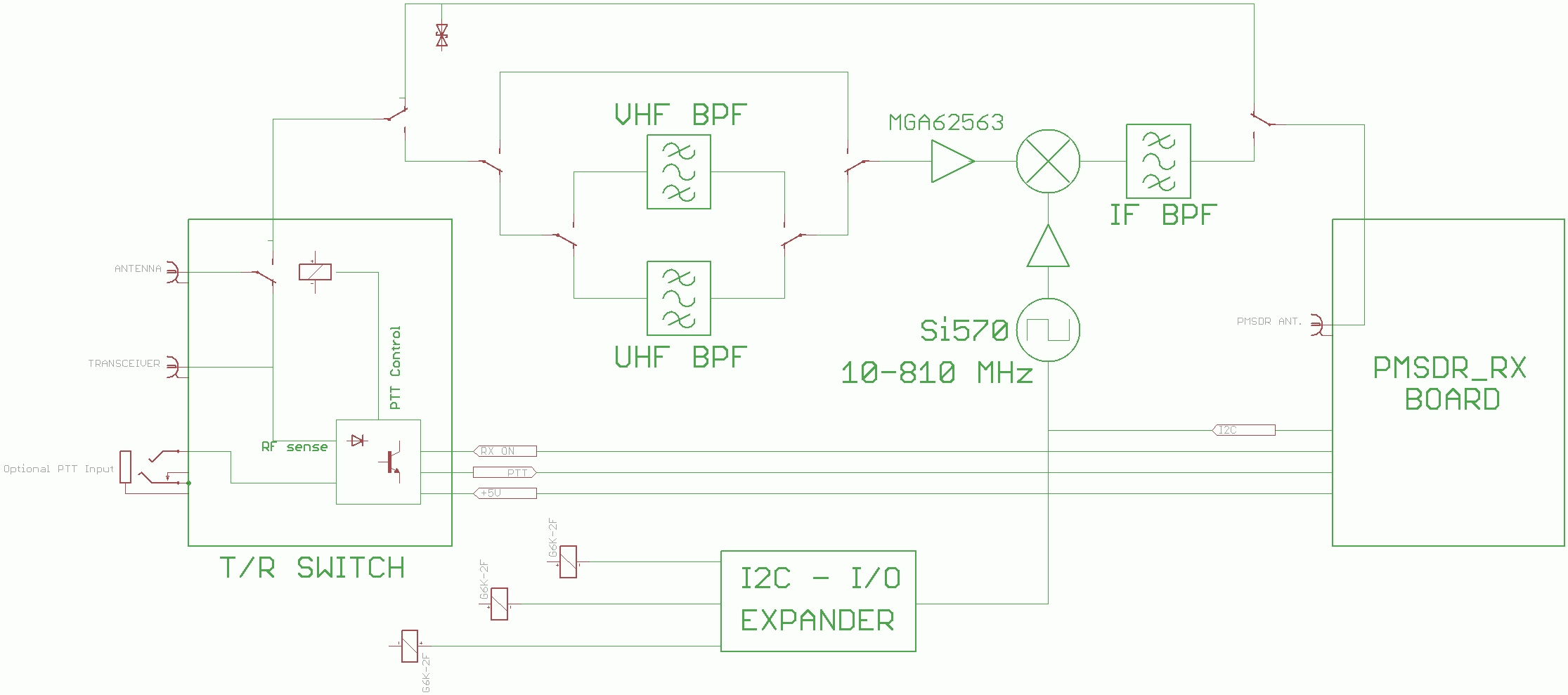
Downconverter board block diagram
Preliminary technical data (with PMSDR):
- sensivity-MDS (bandwitdh = 2400 Hz) @ (S+N)/N= 3dB : -133,5dBm @144MHz / -132dBm @433MHz
- Input IP3 = +1,5dBm
- Conversion gain: about 11 dB
- Power supply: USB (+5V) – 160 mA
Switch preliminary technical data:
- Transceiver BNC-F Connector
- Antenna BNC-F Connector
- PTT Control line 3,5mm jack
- Frequency range: 0,1 -500MHz
- Maximum TX power: 100W (UHF 50W)
- RF sense threshold: <2W
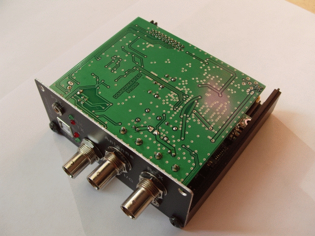
| DOWNCONVERTER Board connections & assembly overview |